
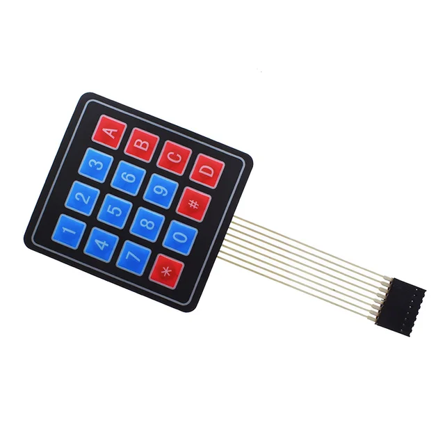
Keypad 4×4 Self-Adhesive 16 key
The 4×4 Matrix Keypad is a versatile and compact input device designed for use in a wide range of electronic and embedded system projects. It consists of 16 individual push buttons arranged in a 4-row by 4-column grid. This configuration allows multiple key inputs to be read using only 8 microcontroller pins, thanks to the matrix scanning technique.
The keypad comes with a self-adhesive backing, making it easy to mount on flat surfaces, enclosures, or project boxes without additional screws or brackets. It is lightweight, durable, and has a sealed surface that resists dust and moisture, making it suitable for both prototyping and final product designs.
This keypad is widely used in Arduino, Raspberry Pi, ESP32, PIC, and other microcontroller-based projects that require numeric or command input, such as password-protected systems, calculators, security locks, or menu navigation systems.
How It Works
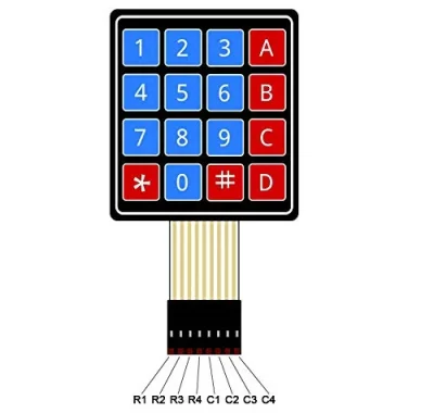
The keypad uses a matrix wiring system where each button connects a unique row and column. By sequentially scanning the rows and reading the columns, a microcontroller can detect which key is pressed. This significantly reduces the number of GPIO pins required compared to wiring each button individually.
For example, pressing the “5” key closes the connection between Row 2 and Column 2. The controller identifies this row-column pair and maps it to the corresponding button value.
Key Features
16 keys arranged in a 4×4 matrix
Self-adhesive backing for easy mounting
Compact, flexible, and durable design
Simple matrix scanning reduces GPIO pin usage
Compatible with Arduino, Raspberry Pi, ESP32, PIC, AVR, ARM, and more
Lightweight and easy to integrate into enclosures
Sealed surface for dust and moisture resistance
Specifications
| Parameter | Value |
|---|---|
| Number of Keys | 16 (4×4 matrix) |
| Operating Voltage | 3.3V – 5V |
| Interface | Matrix (row/column) – |
| Connector Type | 8-pin header |
| Cable Length | ~85 mm |
| Keypad Size | ~70 mm × 77 mm |
| Mounting | Self-adhesive backing |
Pin Configuration
| Pin | Name | Description |
|---|---|---|
| 1 | R1 | Row 1 input/output |
| 2 | R2 | Row 2 input/output |
| 3 | R3 | Row 3 input/output |
| 4 | R4 | Row 4 input/output |
| 5 | C1 | Column 1 input/output |
| 6 | C2 | Column 2 input/output |
| 7 | C3 | Column 3 input/output |
| 8 | C4 | Column 4 input/output |