Description
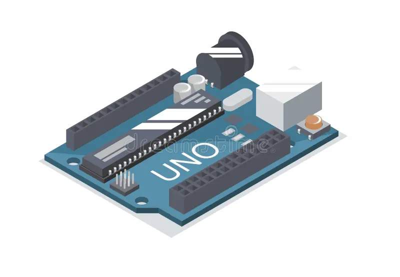
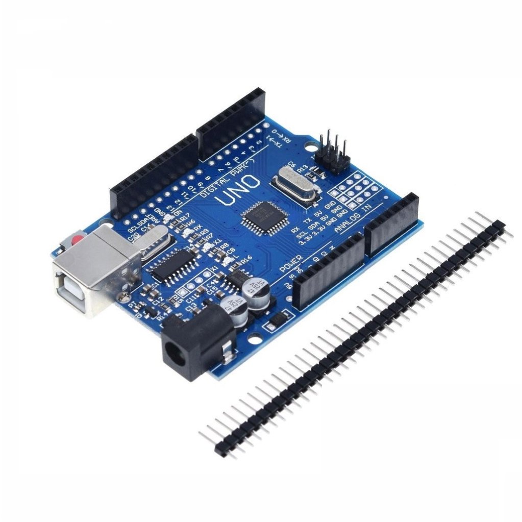
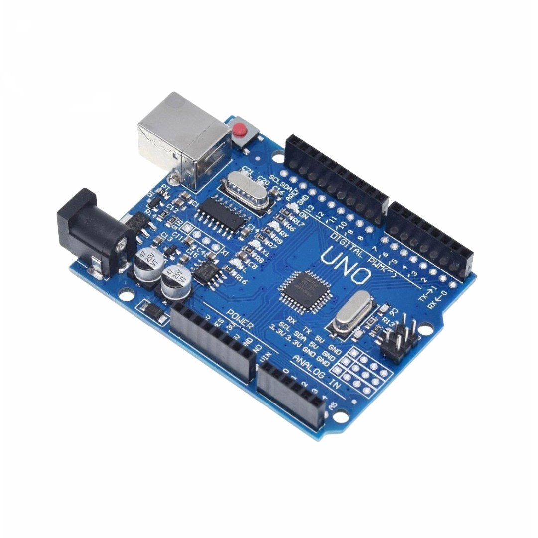
The Uno R3 SMD is an Arduino-compatible version of the latest R3 edition of the popular Uno board. It’s one of the most commonly used development boards among hobbyists. Unlike the original design, this version uses an SMD microprocessor instead of the traditional DIP package. It also includes some extra features.
Package Includes
Uno R3 SMD (Arduino compatible)
1 x 40 break-away male header strip
Key Features
ATmega328 processor @ 16MHz
CH340 Serial to USB converter
32KB Flash memory
14 Digital I/O pins
6 PWM (shared with digital I/O)
6 Analog inputs (can act as digital I/O — up to 20 total)
1 Hardware serial port
5V Operation
Power Supply
The board operates at 5V, which can be supplied through either an external adapter or the USB port. The board automatically switches to the available power source.
If you’re using an external power source, it’s best to choose a voltage between 7V and 12V. Using higher voltages will put more load on the onboard regulator and may cause overheating.
Expansion Options
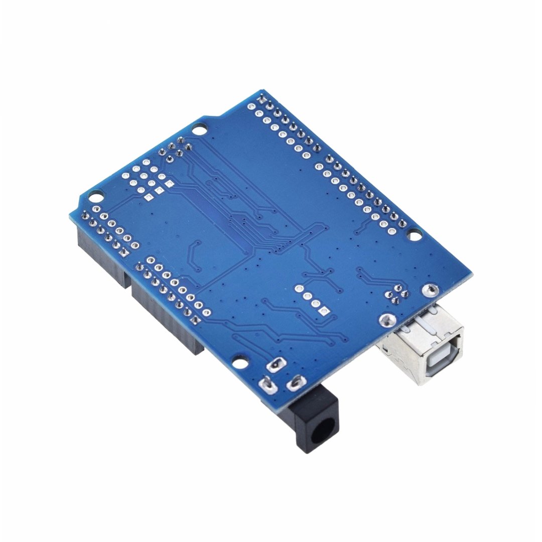
A great feature of this board is its flexibility with pin headers. In addition to the standard female headers, there’s a second row of holes next to them.
You can solder male headers, female headers, or wires to these holes — either on the top or bottom side of the board.
Note: If you solder male headers to the bottom, the board won’t fit into a breadboard due to pin spacing differences.
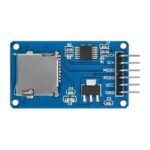
Additional Connectivity
The board includes extra solder points that offer access to:
I2C (SCL/SDA)
Serial (TX/RX)
3.3V, 5V, and GND
This makes wiring more flexible, especially in embedded projects.
Programming
Like any Arduino-compatible board, you can program the Uno R3 SMD using the Arduino IDE via USB.
DIP vs. SMD Version
We also offer the original Uno with a DIP processor in a socket.
Pros: Easy to replace if damaged.
Cons: DIP parts are harder to find and more expensive than SMD versions.
Our Evaluation
We tested these Uno R3 SMD boards and found them to be well-built clones.
One standout feature is the option to add a second row of headers. If you’re going old-school, you can even use wire-wrapping for more secure connections in permanent setups.
The board uses the CH340 chip for USB communication. In most cases, your computer will detect it automatically.
If not, you may need to install the driver manually.
Driver Installation Guide (CH340)
In case the board isn’t detected, here’s how to install the CH340 driver:
Windows:
Download the Windows CH340 Driver
Unzip the downloaded file
Run the installer
After installation, open the Arduino IDE
Go to Tools > Serial Port, and select the COM port for your board
The COM port number may vary based on your system.
For other operating systems, just search for “Arduino CH340 driver” with your OS name. You’ll find multiple sources.
Technical Specifications
| Parameter | Value |
|---|---|
| Microcontroller | ATmega328P |
| Serial to USB | CH340 |
| Operating Voltage | 5V |
| Input Voltage (recommended) | 7–12V |
| Digital I/O Pins | 14 |
| PWM Pins | 6 (shared) |
| Analog Inputs | 6 |
| Max Current per I/O Pin | 20mA |
| Max Current from 3.3V Pin | 50mA |
| Flash Memory | 32 KB |
| SRAM | 2 KB |
| EEPROM | 1 KB |
| Clock Speed | 16 MHz |
| Built-in LED | Pin 13 |
| USB Connector | USB-B Type |
| PCB Dimensions | 68.8 x 53.4 mm |
| Full Dimensions | 77 x 53.4 mm |
| Manufacturer | China |
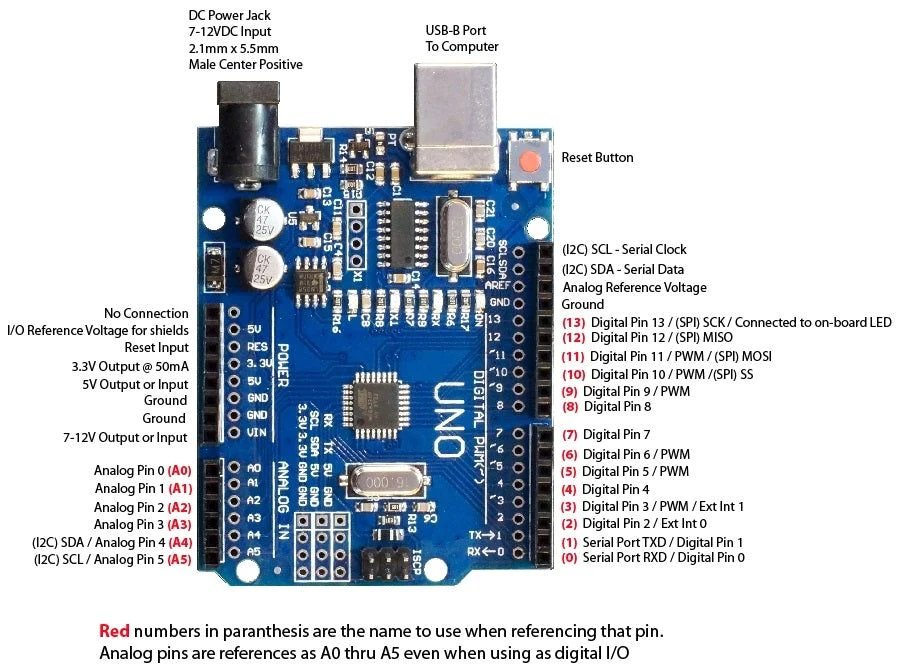
Pin Out:
Watch a video walkthrough of this process
we’ll show you how to install CH340 drivers on multiple operating systems if you need them. The driver should automatically install on most operating systems. However, there is a wide range of operating systems out there. You may need to install drivers the first time you connect the chip to your computer’s USB port or when there are operating system updates.
Windows
- Download the Windows CH340 Driver
- Unzip the file
- Run the installer that you unzipped
- In the Arduino IDE when the CH340 is connected you will see a COM Port in the Tools > Serial Port menu, the COM number for your device may vary depending on your system.