

4060 IC 14-Stage Oscillator Binary Counter
The CD4060BE is a 14-stage binary ripple counter with an integrated oscillator, designed for precision timing and frequency division applications. Engineers use it to generate accurate time delays and divide input clock signals without needing external counter chains. The IC combines a Schmitt-trigger oscillator with internal reset and counter logic to simplify design and save board space.
You can configure the oscillator with just a few passive components (resistors and a capacitor), allowing you to set specific frequencies with minimal effort. Once the oscillator begins running, the internal binary counter stages divide the frequency down to produce multiple timing intervals, each available on dedicated output pins.
Key Features
14-stage binary ripple counter
Integrated oscillator with adjustable RC timing
Built-in Schmitt-trigger input for noise immunity
Wide supply voltage range: 3V to 15V
Compatible with TTL and CMOS logic
Low power consumption with high noise immunity
Buffered outputs for stable logic levels
Reset pin for counter initialization
DIP-16 package for easy prototyping
Ideal for time delays, frequency division, and event timing
Product Specifications
| Specification | Value |
|---|---|
| Professional Name | CD4060BE |
| Function Type | 14-stage Binary Counter with Oscillator |
| Technology | CMOS |
| Logic Type | Ripple Counter with Schmitt Oscillator |
| Supply Voltage | 3V to 15V ‘ |
| Output Count Stages | Q4 to Q14 (varies by configuration) |
| Oscillator | RC Configurable with Ext. Components |
| Typical Osc. Frequency | User-defined based on RC values |
| Reset Input | Active-high asynchronous reset |
| Power Dissipation | Very Low (CMOS) |
| Operating Temperature | -55°C to +125°C |
| Package | DIP-16 |
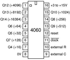
Pin Configuration (DIP-16)
| Pin No. | Name | Description |
|---|---|---|
| 1 | Q12 | Output Stage Q12 |
| 2 | Q13 | Output Stage Q13 |
| 3 | Q14 | Output Stage Q14 |
| 4 | Q6 | Output Stage Q6 |
| 5 | Q5 | Output Stage Q5 |
| 6 | Q4 | Output Stage Q4 |
| 7 | RESET | Asynchronous Reset Input (active high) |
| 8 | GND | Ground |
| 9 | CLK INH | Clock Inhibit (tie low to enable clock) |
| 10 | CLK | Oscillator Clock Input (via RC) |
| 11 | R | Oscillator Reset (RC configuration) |
| 12 | C | Capacitor pin for oscillator |
| 13 | Q10 | Output Stage Q10 |
| 14 | Q11 | Output Stage Q11 |
| 15 | Q7 | Output Stage Q7 |
| 16 | VDD | Positive Supply |
Applications
Timer circuits and time delays
Frequency divider and digital clocks
LED chasers and light control systems
Sequential timing in automation systems
Pulse generation and timing control
Watchdog timer and reset circuits
Alarm systems and delay-based relays
Frequency control in communication circuits