
4053 IC Triple 2-Channel Analog Demultiplexer
The CD4053BE is a triple 2-channel analog multiplexer/demultiplexer that enables the routing of both analog and digital signals with high precision and low distortion. Each of the three independent switches allows bidirectional signal flow between two terminals, controlled by a single select line. This flexibility makes the CD4053BE ideal for signal switching, routing, and multiplexing tasks in a wide range of analog and digital systems.
Built using CMOS technology, the CD4053BE offers high noise immunity, low power consumption, and compatibility with a broad range of supply voltages, from 3V to 15V. It features low ON resistance and minimal crosstalk between channels, ensuring reliable signal integrity in complex circuit designs. Engineers often use this IC in sensor selection, data acquisition, waveform generation, audio switching, and logic-level signal control.
Key Features
Triple 2-channel analog multiplexer/demultiplexer
Bidirectional analog/digital signal switching
Single-pole double-throw (SPDT) configuration
Wide supply voltage: 3V to 15V
Low ON resistance and fast switching
Minimal crosstalk between channels
Low power CMOS technology
Compatible with TTL and CMOS logic
DIP-16 package for easy prototyping
Rail-to-rail signal handling support
Product Specifications
| Specification | Value |
|---|---|
| Professional Name | CD4053BE |
| Function Type | Triple 2-Channel Analog Switch |
| Technology | CMOS |
| Signal Type | Analog and Digital |
| Switching Configuration | 3 x SPDT |
| Supply Voltage (VDD) | 3V to 15V |
| Control Inputs | A, B, C, INH |
| ON Resistance | ~125 Ohms @ VDD = 5V |
| OFF Channel Leakage | < 0.1 μA ‘ |
| Crosstalk | Low (< -60 dB typical) |
| Operating Temp. Range | -55°C to +125°C |
| Max Propagation Delay | ~200 ns |
| Package Type | DIP-16 |
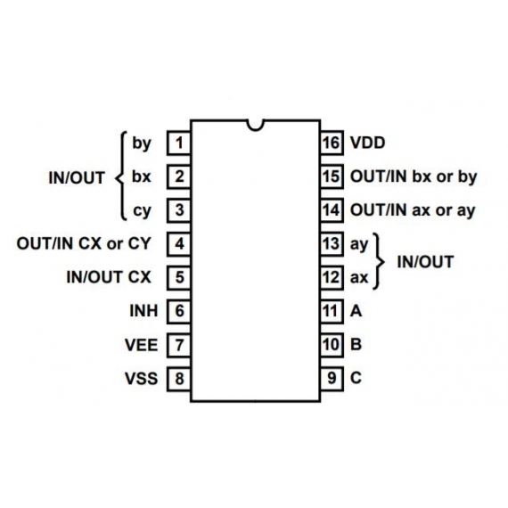
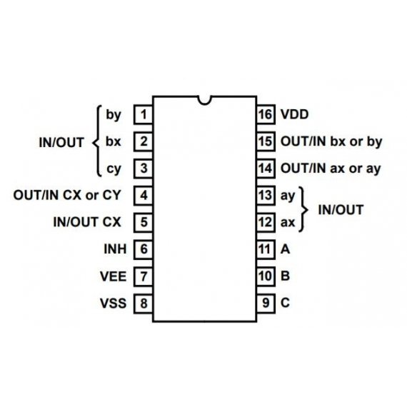
Pin Configuration (DIP-16)
| Pin No. | Name | Description |
|---|---|---|
| 1 | X | Channel X output/input |
| 2 | Y | Channel Y output/input |
| 3 | Z | Channel Z output/input |
| 4 | X0 | Channel X, input 0 |
| 5 | X1 | Channel X, input 1 |
| 6 | Y0 | Channel Y, input 0 |
| 7 | Y1 | Channel Y, input 1 |
| 8 | GND | Ground |
| 9 | Z0 | Channel Z, input 0 |
| 10 | Z1 | Channel Z, input 1 |
| 11 | INH | Inhibit (active high disables switches) |
| 12 | C | Control input for switch Z |
| 13 | B | Control input for switch Y |
| 14 | A | Control input for switch X |
| 15 | VEE | Negative Supply (optional for analog) |
| 16 | VDD | Positive Supply Voltage |
Applications
Audio and video signal switching
Data acquisition systems
Sensor input selection
Instrumentation and waveform generation
Industrial control and automation
Microcontroller and FPGA interfacing
Low-power analog/digital switching